How to Build Your Own 3D Printed Raspberry Pi Robot
Building your own robot is one of the most satisfying things you can do. It combines mechanical, electrical, and programming skills together in a way few projects do.
I’ve been building robots for a couple of years now and love to expand my knowledge and skills by using different controller boards, motors, wheels, and sensors to detect the world around the robot.
Raspberry Pi robots are particularly impressive. The Raspberry Pi provides the robot with the full power of Linux and a plethora of Python libraries. With all of this power, it means we can add advanced machine learning, computer vision, and Internet connectivity into the mix. All this at an affordable price point and tiny form factor too.
Building Raspberry Pi robots from kits, such as Pimoroni’s Trilobot, or from a custom design such as Explora, is fun and helps develop skills such as programming in Python, mechanical design, and electronics. People love playing with robots and teaching them to perform tasks and move around the environment unaided.
Explora uses the Pimoroni Explorer pHAT (we included the Explorer HAT Pro in our best Raspberry Pi HATs guide) to control the motors and has a handy Python library to make this simple. Explora is programmed in Python and uses sensors to avoid obstacles and follow your handExplora can also be remotely controlled over Wi-Fi.
Explora can detect objects in front of it using an HC-SR04 ultrasonic range finder module. These modules come in either a 5v version or a 3.3v version (HCSR04+ or HC-SR04P). The Explorer pHAT is 5v tolerant, but it’s best to get the HC-SR04+ or HC-SR04-P version to be on the safe side. Using the 5v version on a Raspberry Pi can damage the board.
Explora was designed using AutoDesk Fusion 360 (opens in new tab). Each piece is a discrete component to enable easier 3D printing. Fusion 360 makes it really easy to export the models into STL files, ready for slicing and then 3D printing. To slice the robot parts (creating the instructions for a 3D printer to print the part) from Fusion 360 I use Cura, and then upload it to OctoPrint to manage the print jobs. The 3D printed parts are designed to be quick and easy to print, and the whole thing is easy to assemble using a couple of screws and wire up.
My personal choice of 3D printer is the Creality Ender 3 Pro and Ender 3 V2.
The electronics for the project are relatively straightforward and involve some soldering. You will need to solder wires to each motor and then to some Male DuPont cables (jumper jerky), one set per motor. You’ll also need something to hold the motors while you solder the wires to the tiny motor connectors which can be a bit tricky if you’ve not done this before. Some “helpful hands” or modeling clay is useful to keep the wires in place.
What You’ll Need
- Soldering iron
- Solder and some flux
- Screwdriver
- Wire cutters
- Wire strippers
- Helping hands – for use with soldering
- A computer with an SD card reader slot
3D Printed Files
Building Explora
The print times for each of Explora’s parts depends on your specific printer and quality settings. I found the files took the following amount of time to print:
| # | Part | Approx Time to Print |
|---|---|---|
| 1. | Chassis | 5 hours 16 minutes |
| 2. | Top Section | 2 hours 22 minutes |
| 3. | Motor Holders – all 4 at once | 3 hours 44 minutes |
| 4. | Camera holder & Camera holder back at once | 2 hours 30 minutes |
I prefer to use PLA+ for my prints and usually have some white or yellow filament already in each printer, ready to go.
To Prepare Explora’s 3D Printed Parts
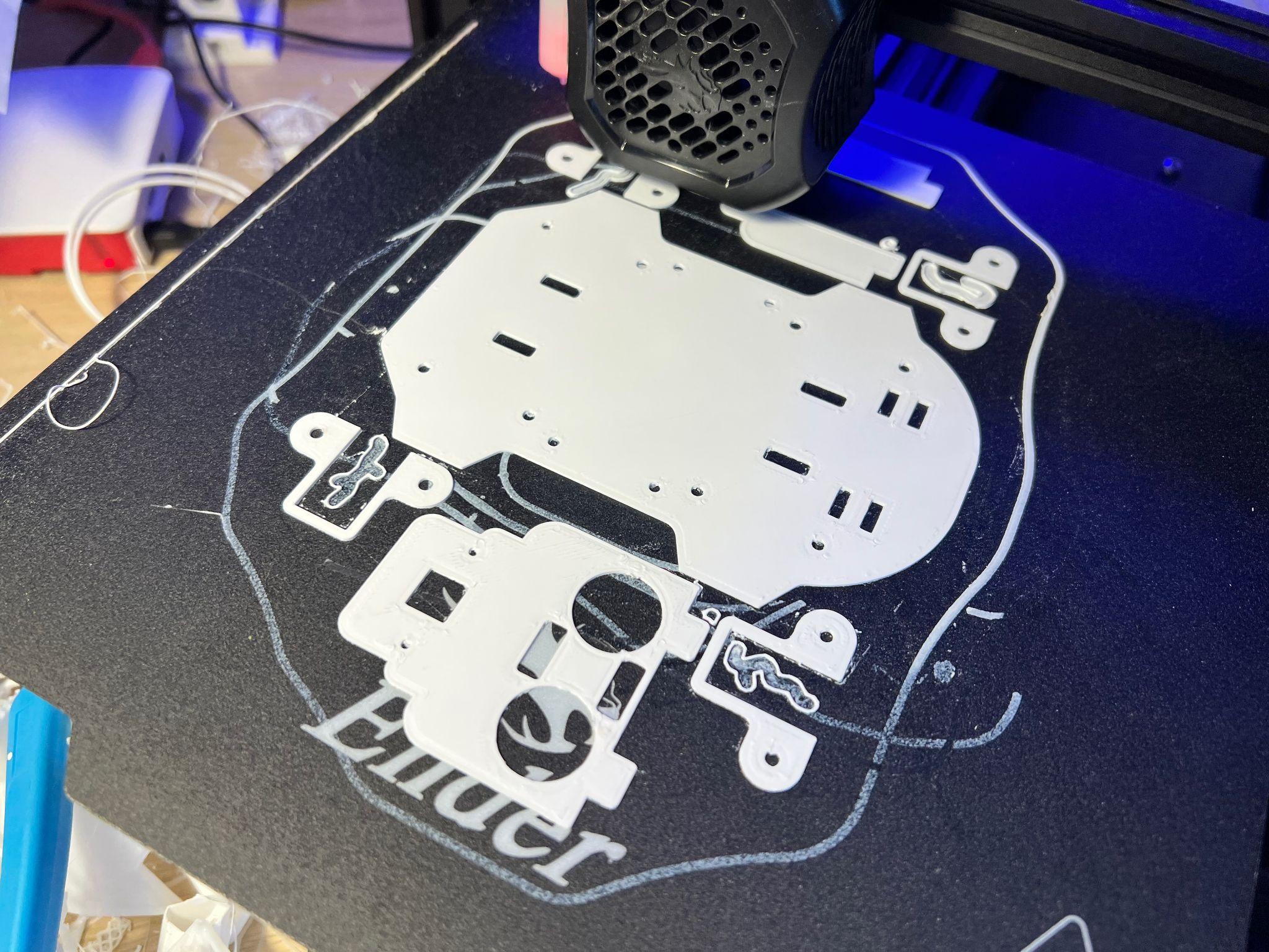
1. Download the 3D printable STL files.
2. Slice the parts using Cura – We like to use Cura, but you are free to use an alternative. and don’t forget to enable supports for the motor holders
3. Transfer the G-Code file from Cura to your 3D Printer. Save the G-Code file to an SD card (if that’s how your 3D printer accepts files) alternatively you can use software such as OctoPrint that runs on a Raspberry Pi and presents a Web-based interface for managing 3D Print jobs. If you’re using OctoPrint you can drag the G-Code file over the left-hand side of the page and it will begin to upload the file, ready for printing.
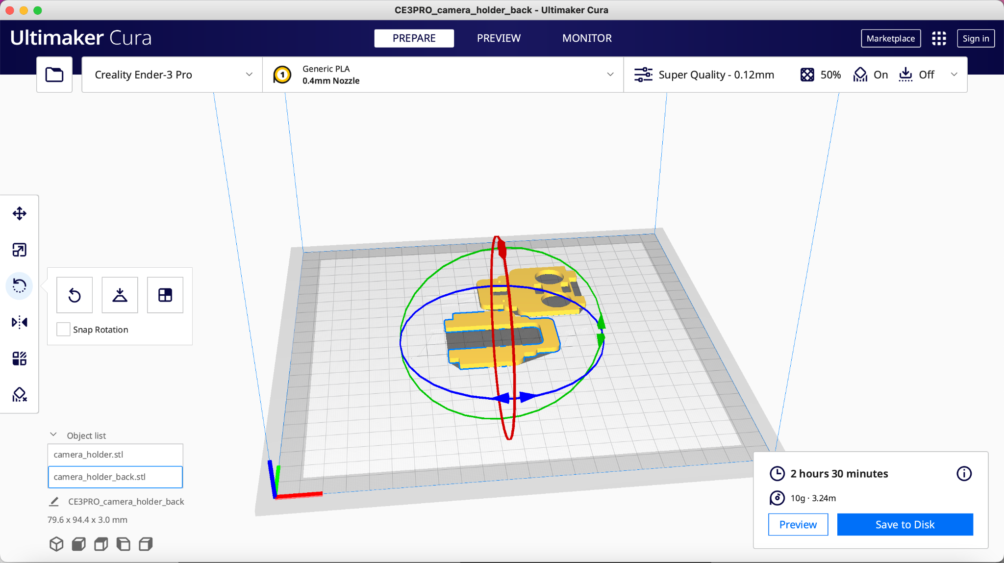
4. Load the G-code and print – We used Octoprint to manage our print jobs
Wiring up Explora
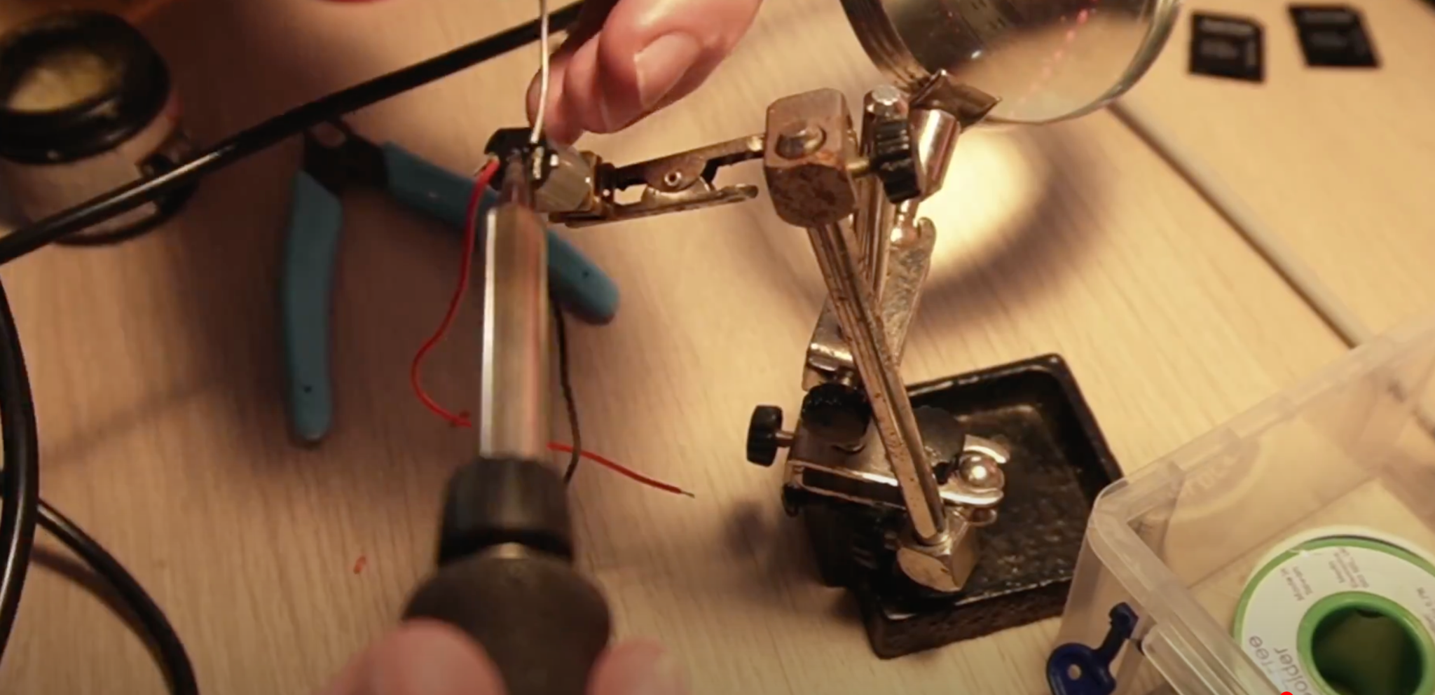
Soldering is an essential maker skill. Learning to solder opens up the entire world of electronics and this project could be your first steps on an exciting journey. If your motors come without any wires attached you’ll need to prepare your own wires and solder these onto the tiny motors. Soldering small parts can be tricky; you will need a steady hand and something to hold the motors while you hold the solder in one hand and the soldering iron in the other.
- Prepare the wires for soldering. Cut four strips of red wire 100mm long each and another four strips of black wire. We should have a pair of black and red wires for each motor.
- Strip wires. Strip about 4mm of wire from each end, exposing the copper wire. A good pair of wire strippers is an essential part of a maker’s toolbox.
- Add Flux. Apply some flux to one end of the wire that will be soldered. Flux helps the solder run around the part correctly. Even if your solder comes with a flux core, a little extra flux will make soldering much easier.
- Tin the wires by adding a small amount of solder to the wires with your soldering iron. Tinning will help the wires solder to the small motor terminals
- Solder the red wire onto the motor terminal – you’ll notice a small + sign above the terminal that is the positive terminal. Take your time, as this can be tricky if you’ve not done it before.
- Push the wire through the hole in the terminal first to make a good mechanical connection and will help hold the wire in place as you solder, then solder the wire to the terminal.
- Repeat the last step for the black wire but this time solder the black wire to the Negative terminal on the motor.
- Twist red and black wires for strength. This will help strengthen the connection if you accidentally tug on the wires.
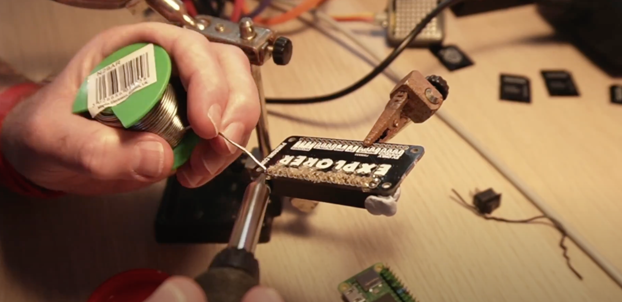
9. Solder the 40 pin header and 20 pin header to the Explorer pHat
Assembly
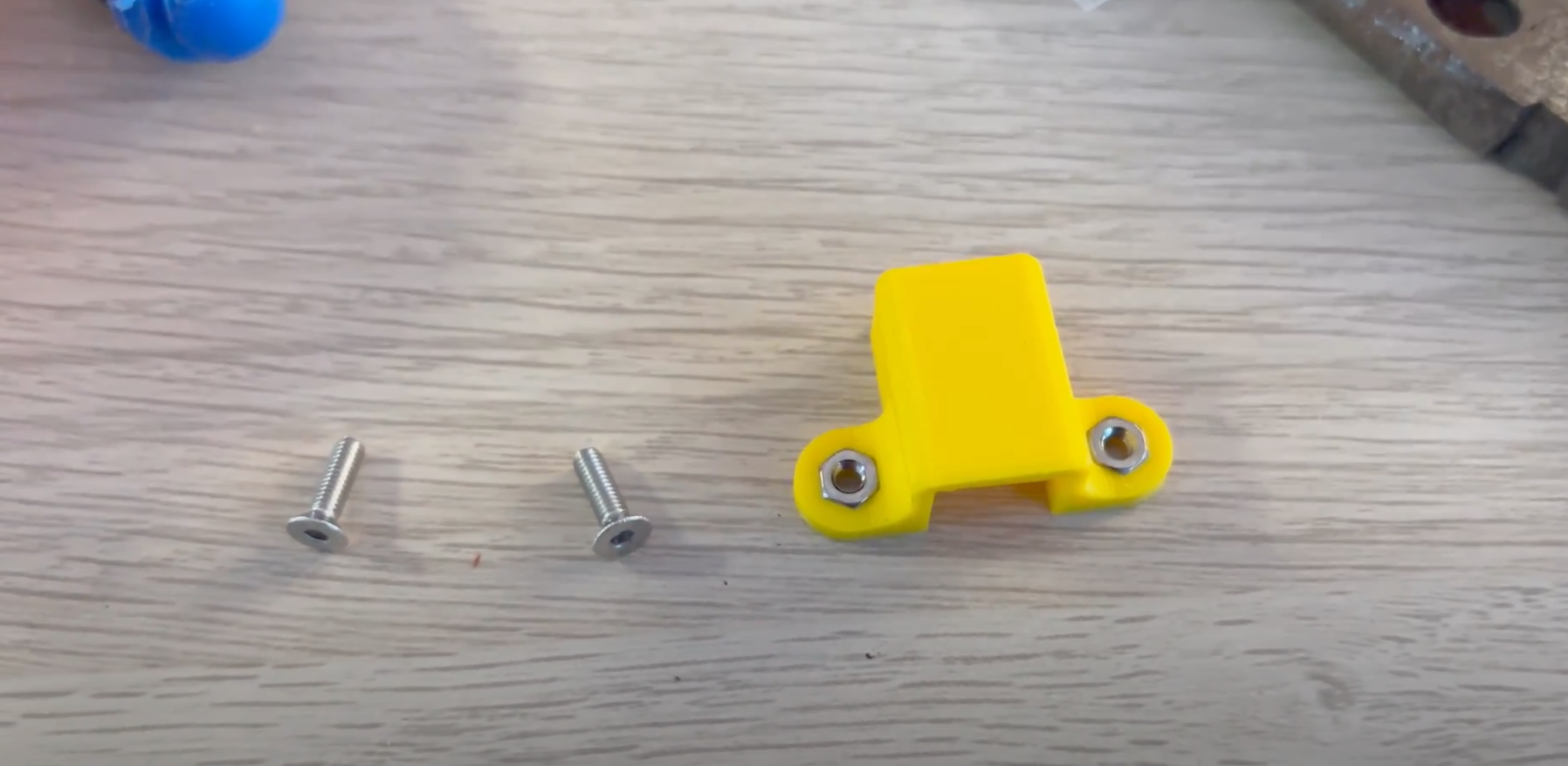
The assembly part of the build won’t take long as it only involves screwing the four motor holders into the chassis using the M2.5 screw and nuts. Then we screw the standoffs into the chassis and Raspberry Pi Zero 2 W, and finally, we attach the Camera holders and top section.
1. Push each motor into a 3D printed motor holder. The motor holders ensure that the motor remains in place on Explora’s chassis. They also offer mechanical rigidity so that the motors do not move position in use.
2. Put a nut into each hexagonal pocket on the motor holder, then screw it from the top side of the chassis through to the motor holder into the nut. Don’t over-tighten as you’ll end up splitting the chassis. This will create a substantial connection between the motor holder and the chassis.
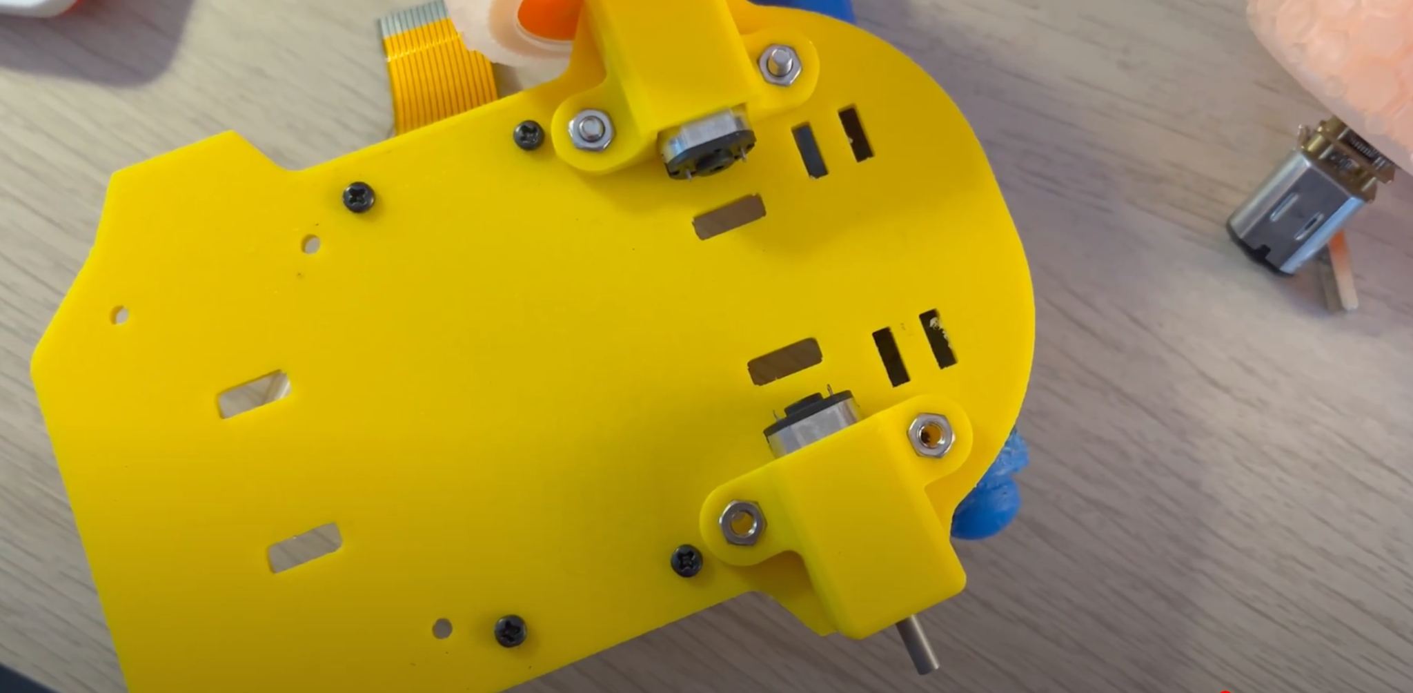
3. Add stand-offs to the chassis by screwing four M2.5 screws into the bottom of the chassis, and screw on a stand-off barrel onto the exposed screw thread until it becomes tight against the chassis.
4. Add four stand-offs to the Raspberry Pi Zero, then attach the Explorer pHat.
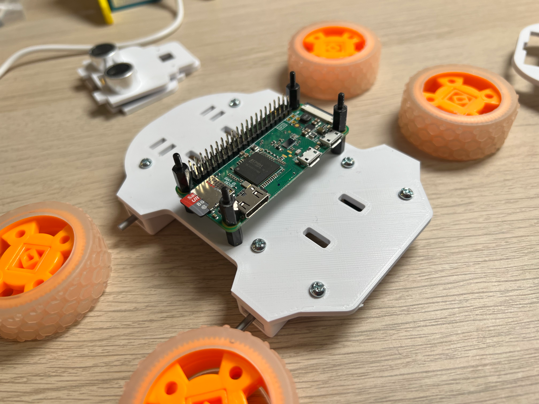
5. Screw the Raspberry Pi Zero into the Chassis stand-offs.
6. Push the Camera Holder into the Chassis. You may need to file off some material if it’s a tight fit.
7. Push the ultrasonic rangefinder into the Camera Holder.
8. Push the female end of the DuPont wires onto the Rangefinder.
9. Push the male end of the DuPont wires onto Explorer pHATs 5v, GND, Output 1 to Trigger, Input 1 to Echo connections.
10. Push the Camera back into the Chassis.
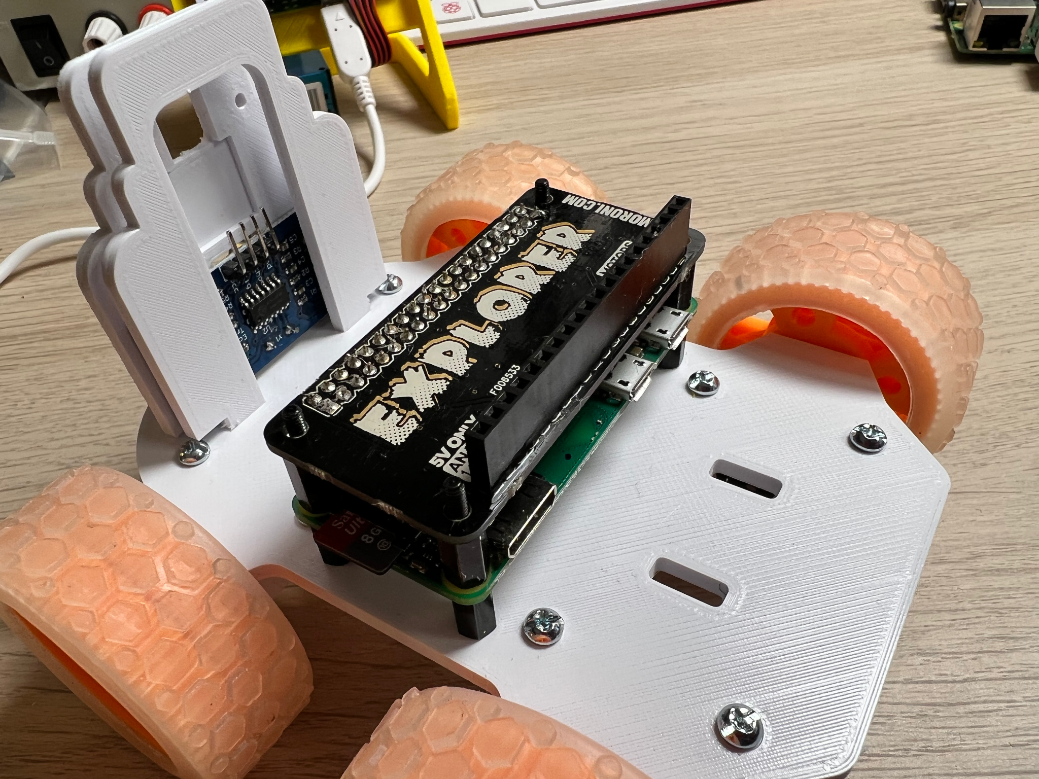
11. Add the last four stand-offs onto the Raspberry Pi Zero
12. Push the Top section over the two camera holders and screw the last 4 M2.5 screws from the top section into the standoffs
13. Using a velcro strap, secure the battery in place.
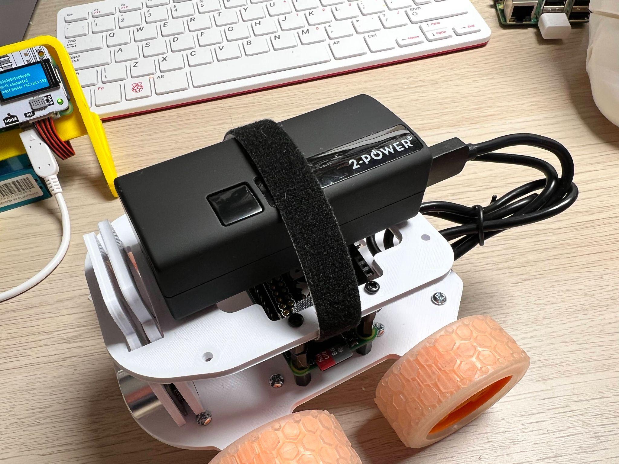
14. Push the 4 wheels onto the ends of the motors. The motor axles are D-shaped, be sure to match the alignment of the axle to the wheel before firmly pushing on.
Preparing the Raspberry Pi
The Raspberry Pi needs a suitable OS to run the Python code to control the motors and optionally capture images. When the Raspberry Pi camera first launched a software library called PiCamera was provided to make it simple to capture stills and video. With the most recent release of Raspberry Pi OS ‘Bullseye’, this old library has been replaced with a library called LibCamera, which is not backward compatible with PiCamera. On the 32-bit release of Bullseye you can choose a legacy camera option from raspi-config, however, this option is not available on the 64bit release.
1. Using the official Raspberry Pi Imager tool, flash the latest 32-bit OS to a micro SD card. We use the 32-bit version of Raspberry Pi OS because the PiCamera library is currently not compatible with the 64-bit version of Raspberry Pi OS.
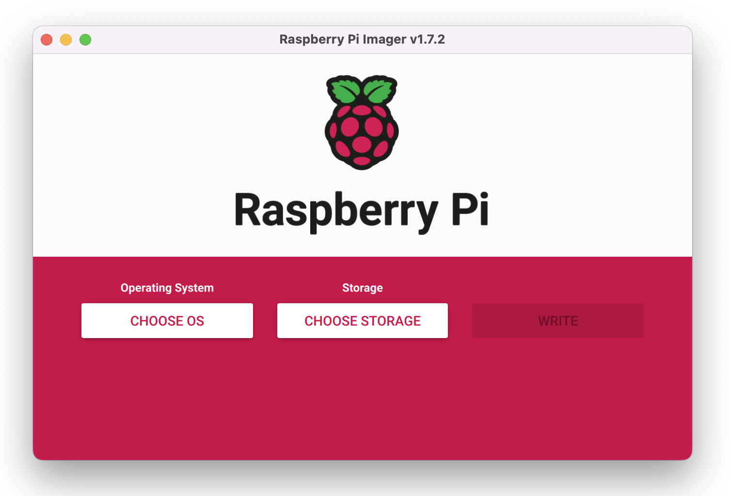
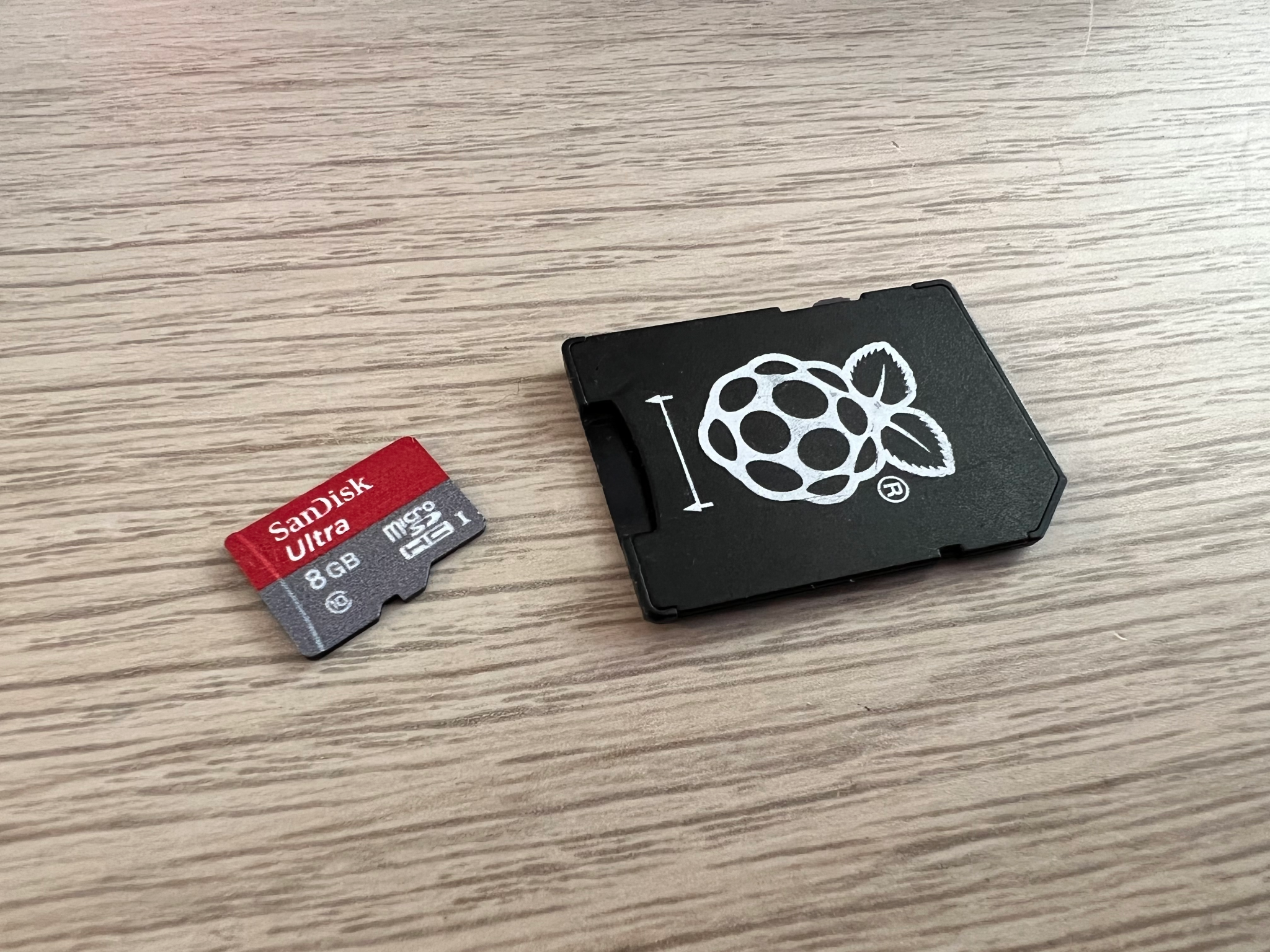
2. Put the micro SD card into the SD card reader slot on your computer.
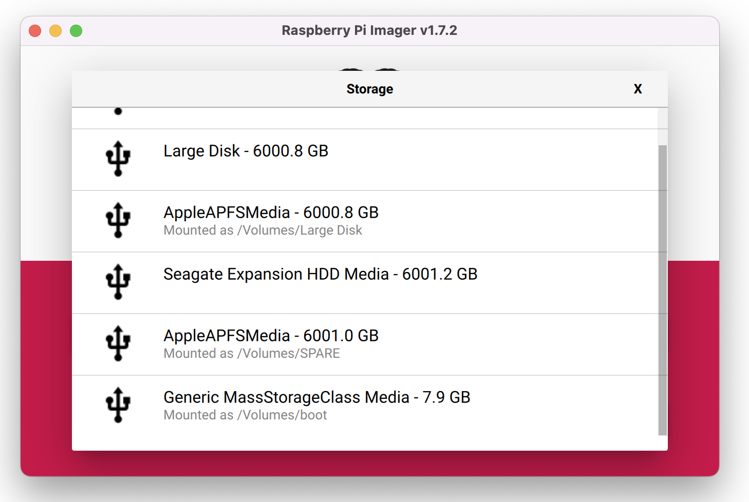
3. Select the micro SD card from the Raspberry Pi imager Storage menu.
4. Click the Advanced (cog) button, and add your Wi-Fi SSID and password details to enable the Raspberry Pi to connect to the wifi automatically.
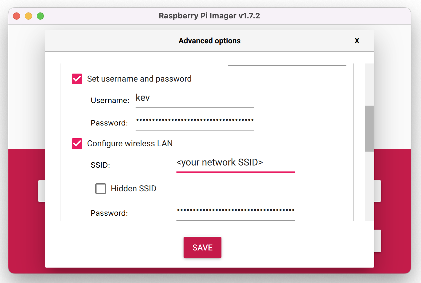
5. Click on Enable SSH and create a username and password. SSH enables a remote to the Raspberry Pi using a terminal without the need for a monitor, keyboard, or mouse.
6. Click Write to begin flashing the image to the micro SD card.
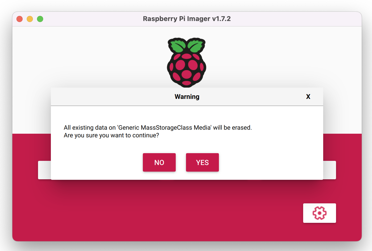
7. Insert the micro SD card into the Raspberry Pi and then power up the Raspberry Pi via the power bank.
Connecting to the Pi
1. Find out the IP address of your Raspberry Pi – you can usually do this from your router (or wherever your router gets its IP addresses from, or by typing:
ssh [email protected]– where `pi` is the username you created earlier in step 5 above.
2. Launch Terminal – if you’re on Windows, you’ll need to use some terminal software such as Putty (https://www.putty.org). Mac and Linux computers have terminal build-in.
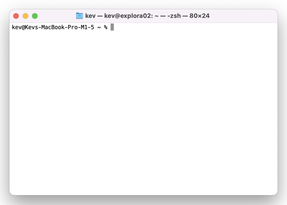
3. SSH to the Raspberry Pi – Type `ssh [email protected]>` into the terminal to connect to the Pi. Linux / Mac users can use the following to SSH into the Pi. If you know the IP address you cal also type `ssh@<ipaddress>`, where <ipaddress> is the IP address of the Raspberry Pi.
ssh [email protected]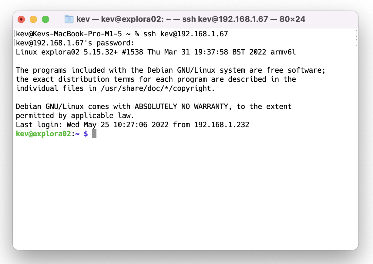
From the Raspberry Pi terminal, clone the Explora software repository. The software is on Github, and we can use the git clone command to download the latest version to our Raspberry Pi:
git clone https://www.github.com/kevinmcaleer/explora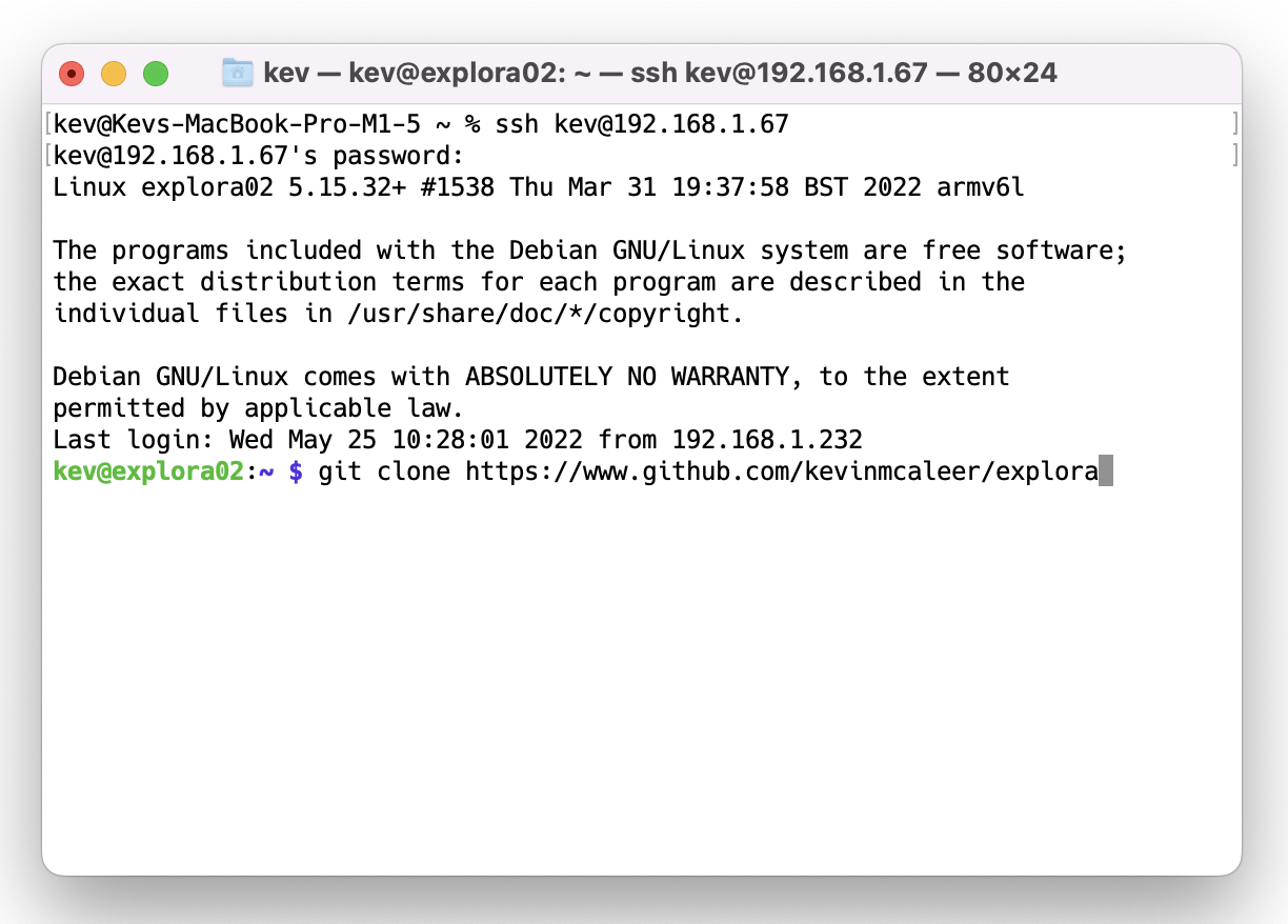
4. Install the Explorer Library via Pimoroni’s online install script.
curl https://get.pimoroni.com/explorerhat | bash4. From the Raspberry Pi terminal, clone the Explora software repository. The software is on Github, and we can use the git clone command to download the latest version to our Raspberry Pi:
curl https://get.pimoroni.com/explorerhat | bashChecklist: What Have We Achieved?
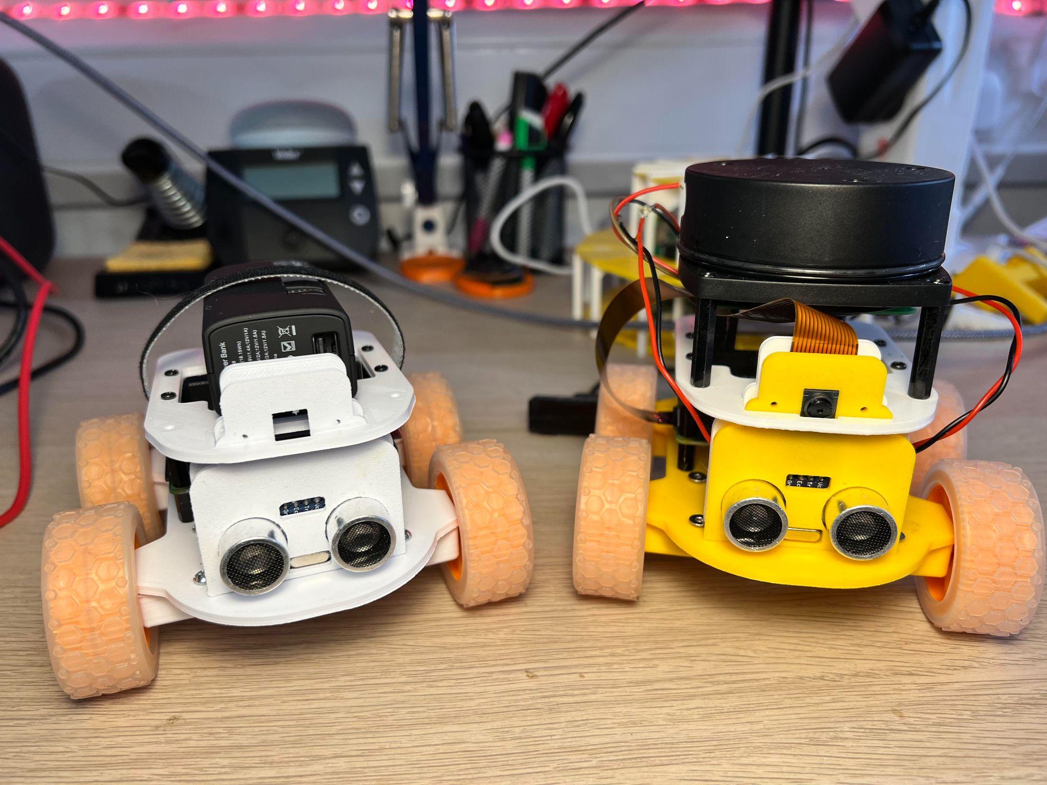
Well done – you’ve completed the first stage and assembled your Robot. You’ve learned:
- how to download, slice and print the Explora 3D printable files,
- how to build and assemble all the parts,
- how to solder wires onto the motors,
- how to prepare the Raspberry Pi OS and install the Explorer Hat Python library
You should now have a fully assembled Explora robot on your desk, ready to receive your first Explora Python program. You can expand the capabilities of Explora by adding a LIDAR laser scanner and Raspberry Pi Camera such as the ones in the picture below.
In the next tutorial, we will create some programs for Explora in Python to move the robot around and detect objects.
Building your own robot is one of the most satisfying things you can do. It combines mechanical, electrical, and programming skills together in a way few projects do.
I’ve been building robots for a couple of years now and love to expand my knowledge and skills by using different controller boards, motors, wheels, and sensors to detect the world around the robot.
Raspberry Pi robots are particularly impressive. The Raspberry Pi provides the robot with the full power of Linux and a plethora of Python libraries. With all of this power, it means we can add advanced machine learning, computer vision, and Internet connectivity into the mix. All this at an affordable price point and tiny form factor too.
Building Raspberry Pi robots from kits, such as Pimoroni’s Trilobot, or from a custom design such as Explora, is fun and helps develop skills such as programming in Python, mechanical design, and electronics. People love playing with robots and teaching them to perform tasks and move around the environment unaided.
Explora uses the Pimoroni Explorer pHAT (we included the Explorer HAT Pro in our best Raspberry Pi HATs guide) to control the motors and has a handy Python library to make this simple. Explora is programmed in Python and uses sensors to avoid obstacles and follow your handExplora can also be remotely controlled over Wi-Fi.
Explora can detect objects in front of it using an HC-SR04 ultrasonic range finder module. These modules come in either a 5v version or a 3.3v version (HCSR04+ or HC-SR04P). The Explorer pHAT is 5v tolerant, but it’s best to get the HC-SR04+ or HC-SR04-P version to be on the safe side. Using the 5v version on a Raspberry Pi can damage the board.
Explora was designed using AutoDesk Fusion 360 (opens in new tab). Each piece is a discrete component to enable easier 3D printing. Fusion 360 makes it really easy to export the models into STL files, ready for slicing and then 3D printing. To slice the robot parts (creating the instructions for a 3D printer to print the part) from Fusion 360 I use Cura, and then upload it to OctoPrint to manage the print jobs. The 3D printed parts are designed to be quick and easy to print, and the whole thing is easy to assemble using a couple of screws and wire up.
My personal choice of 3D printer is the Creality Ender 3 Pro and Ender 3 V2.
The electronics for the project are relatively straightforward and involve some soldering. You will need to solder wires to each motor and then to some Male DuPont cables (jumper jerky), one set per motor. You’ll also need something to hold the motors while you solder the wires to the tiny motor connectors which can be a bit tricky if you’ve not done this before. Some “helpful hands” or modeling clay is useful to keep the wires in place.
What You’ll Need
- Soldering iron
- Solder and some flux
- Screwdriver
- Wire cutters
- Wire strippers
- Helping hands – for use with soldering
- A computer with an SD card reader slot
3D Printed Files
Building Explora
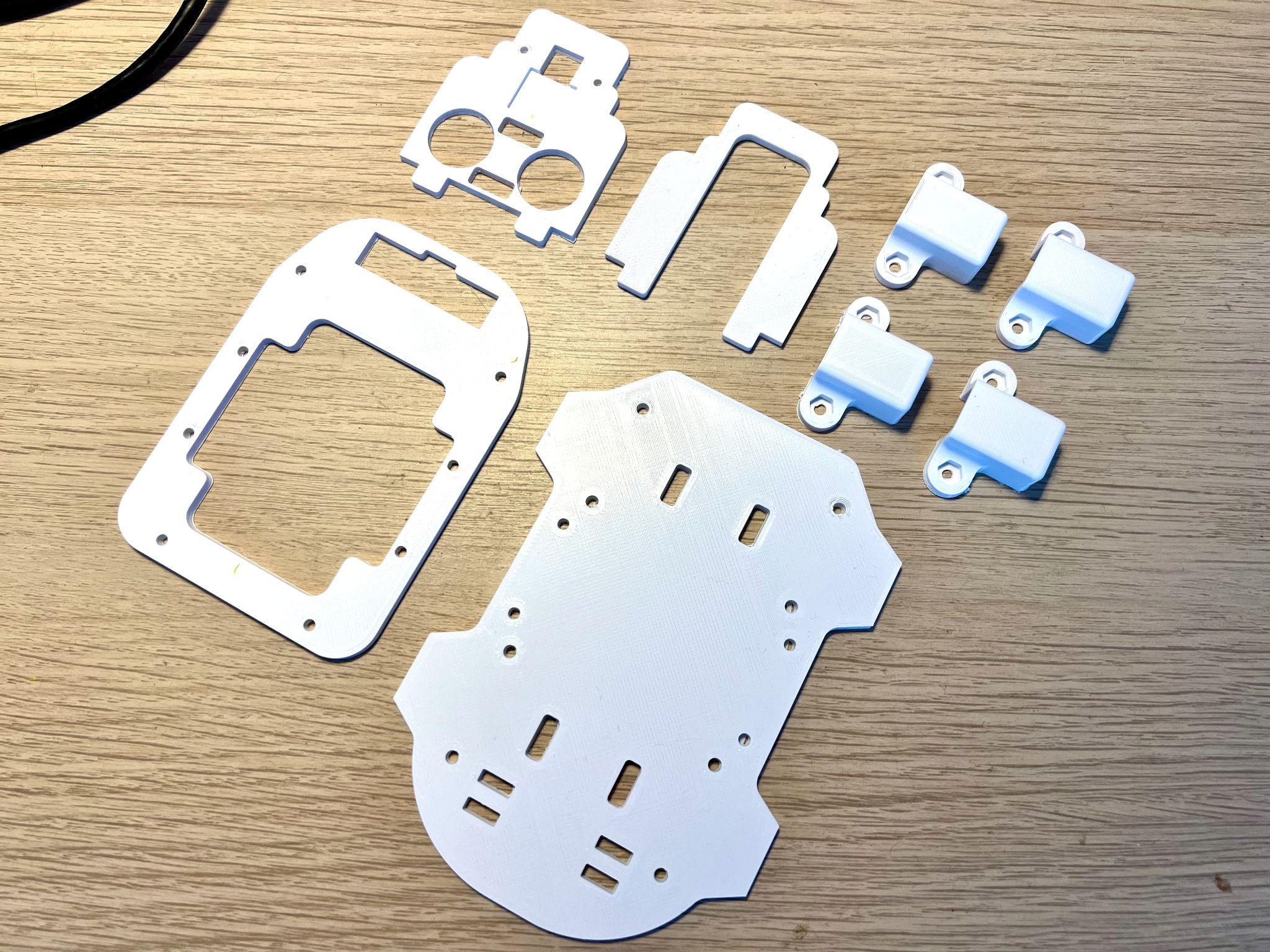
The print times for each of Explora’s parts depends on your specific printer and quality settings. I found the files took the following amount of time to print:
| # | Part | Approx Time to Print |
|---|---|---|
| 1. | Chassis | 5 hours 16 minutes |
| 2. | Top Section | 2 hours 22 minutes |
| 3. | Motor Holders – all 4 at once | 3 hours 44 minutes |
| 4. | Camera holder & Camera holder back at once | 2 hours 30 minutes |
I prefer to use PLA+ for my prints and usually have some white or yellow filament already in each printer, ready to go.
To Prepare Explora’s 3D Printed Parts

1. Download the 3D printable STL files.
2. Slice the parts using Cura – We like to use Cura, but you are free to use an alternative. and don’t forget to enable supports for the motor holders
3. Transfer the G-Code file from Cura to your 3D Printer. Save the G-Code file to an SD card (if that’s how your 3D printer accepts files) alternatively you can use software such as OctoPrint that runs on a Raspberry Pi and presents a Web-based interface for managing 3D Print jobs. If you’re using OctoPrint you can drag the G-Code file over the left-hand side of the page and it will begin to upload the file, ready for printing.

4. Load the G-code and print – We used Octoprint to manage our print jobs
Wiring up Explora

Soldering is an essential maker skill. Learning to solder opens up the entire world of electronics and this project could be your first steps on an exciting journey. If your motors come without any wires attached you’ll need to prepare your own wires and solder these onto the tiny motors. Soldering small parts can be tricky; you will need a steady hand and something to hold the motors while you hold the solder in one hand and the soldering iron in the other.
- Prepare the wires for soldering. Cut four strips of red wire 100mm long each and another four strips of black wire. We should have a pair of black and red wires for each motor.
- Strip wires. Strip about 4mm of wire from each end, exposing the copper wire. A good pair of wire strippers is an essential part of a maker’s toolbox.
- Add Flux. Apply some flux to one end of the wire that will be soldered. Flux helps the solder run around the part correctly. Even if your solder comes with a flux core, a little extra flux will make soldering much easier.
- Tin the wires by adding a small amount of solder to the wires with your soldering iron. Tinning will help the wires solder to the small motor terminals
- Solder the red wire onto the motor terminal – you’ll notice a small + sign above the terminal that is the positive terminal. Take your time, as this can be tricky if you’ve not done it before.
- Push the wire through the hole in the terminal first to make a good mechanical connection and will help hold the wire in place as you solder, then solder the wire to the terminal.
- Repeat the last step for the black wire but this time solder the black wire to the Negative terminal on the motor.
- Twist red and black wires for strength. This will help strengthen the connection if you accidentally tug on the wires.

9. Solder the 40 pin header and 20 pin header to the Explorer pHat

Assembly
The assembly part of the build won’t take long as it only involves screwing the four motor holders into the chassis using the M2.5 screw and nuts. Then we screw the standoffs into the chassis and Raspberry Pi Zero 2 W, and finally, we attach the Camera holders and top section.
1. Push each motor into a 3D printed motor holder. The motor holders ensure that the motor remains in place on Explora’s chassis. They also offer mechanical rigidity so that the motors do not move position in use.
2. Put a nut into each hexagonal pocket on the motor holder, then screw it from the top side of the chassis through to the motor holder into the nut. Don’t over-tighten as you’ll end up splitting the chassis. This will create a substantial connection between the motor holder and the chassis.

3. Add stand-offs to the chassis by screwing four M2.5 screws into the bottom of the chassis, and screw on a stand-off barrel onto the exposed screw thread until it becomes tight against the chassis.
4. Add four stand-offs to the Raspberry Pi Zero, then attach the Explorer pHat.

5. Screw the Raspberry Pi Zero into the Chassis stand-offs.
6. Push the Camera Holder into the Chassis. You may need to file off some material if it’s a tight fit.
7. Push the ultrasonic rangefinder into the Camera Holder.
8. Push the female end of the DuPont wires onto the Rangefinder.
9. Push the male end of the DuPont wires onto Explorer pHATs 5v, GND, Output 1 to Trigger, Input 1 to Echo connections.
10. Push the Camera back into the Chassis.

11. Add the last four stand-offs onto the Raspberry Pi Zero
12. Push the Top section over the two camera holders and screw the last 4 M2.5 screws from the top section into the standoffs
13. Using a velcro strap, secure the battery in place.

14. Push the 4 wheels onto the ends of the motors. The motor axles are D-shaped, be sure to match the alignment of the axle to the wheel before firmly pushing on.
Preparing the Raspberry Pi
The Raspberry Pi needs a suitable OS to run the Python code to control the motors and optionally capture images. When the Raspberry Pi camera first launched a software library called PiCamera was provided to make it simple to capture stills and video. With the most recent release of Raspberry Pi OS ‘Bullseye’, this old library has been replaced with a library called LibCamera, which is not backward compatible with PiCamera. On the 32-bit release of Bullseye you can choose a legacy camera option from raspi-config, however, this option is not available on the 64bit release.
1. Using the official Raspberry Pi Imager tool, flash the latest 32-bit OS to a micro SD card. We use the 32-bit version of Raspberry Pi OS because the PiCamera library is currently not compatible with the 64-bit version of Raspberry Pi OS.

2. Put the micro SD card into the SD card reader slot on your computer.

3. Select the micro SD card from the Raspberry Pi imager Storage menu.

4. Click the Advanced (cog) button, and add your Wi-Fi SSID and password details to enable the Raspberry Pi to connect to the wifi automatically.

5. Click on Enable SSH and create a username and password. SSH enables a remote to the Raspberry Pi using a terminal without the need for a monitor, keyboard, or mouse.
6. Click Write to begin flashing the image to the micro SD card.

7. Insert the micro SD card into the Raspberry Pi and then power up the Raspberry Pi via the power bank.
Connecting to the Pi
1. Find out the IP address of your Raspberry Pi – you can usually do this from your router (or wherever your router gets its IP addresses from, or by typing:
ssh [email protected]– where `pi` is the username you created earlier in step 5 above.
2. Launch Terminal – if you’re on Windows, you’ll need to use some terminal software such as Putty (https://www.putty.org). Mac and Linux computers have terminal build-in.

3. SSH to the Raspberry Pi – Type `ssh [email protected]>` into the terminal to connect to the Pi. Linux / Mac users can use the following to SSH into the Pi. If you know the IP address you cal also type `ssh@<ipaddress>`, where <ipaddress> is the IP address of the Raspberry Pi.
ssh [email protected]
From the Raspberry Pi terminal, clone the Explora software repository. The software is on Github, and we can use the git clone command to download the latest version to our Raspberry Pi:
git clone https://www.github.com/kevinmcaleer/explora
4. Install the Explorer Library via Pimoroni’s online install script.
curl https://get.pimoroni.com/explorerhat | bash4. From the Raspberry Pi terminal, clone the Explora software repository. The software is on Github, and we can use the git clone command to download the latest version to our Raspberry Pi:
curl https://get.pimoroni.com/explorerhat | bashChecklist: What Have We Achieved?

Well done – you’ve completed the first stage and assembled your Robot. You’ve learned:
- how to download, slice and print the Explora 3D printable files,
- how to build and assemble all the parts,
- how to solder wires onto the motors,
- how to prepare the Raspberry Pi OS and install the Explorer Hat Python library
You should now have a fully assembled Explora robot on your desk, ready to receive your first Explora Python program. You can expand the capabilities of Explora by adding a LIDAR laser scanner and Raspberry Pi Camera such as the ones in the picture below.
In the next tutorial, we will create some programs for Explora in Python to move the robot around and detect objects.
