A Beginner-Friendly Introduction to Kubernetes | by David Chong | Jun, 2022
It doesn’t have to be that complicated, right?
With a hands-on MLFlow deployment example
If you’re reading this article, it’s likely because you’ve heard this buzzword “Kubernetes” (K8s) and you’re likely to be in the technology space. You would also likely have some idea of what containerization (or synonymously known as Docker / dockerization) is, so I would skip over the details of that and jump straight into what K8s is.
In a nutshell, K8s is simply a container orchestration framework. What this essentially means is that K8s is a system designed to automate the lifecycle of containerized applications — from predictability, scalability to availability.
Why do we even need Kubernetes?
The driving reason behind the rise and need for K8s stems from the increasing use of microservices, away from traditional monolithic-type applications. As a result, containers provide the perfect host for these individual microservices as containers manage dependencies, are independent, OS-agnostic and ephemeral, amongst other benefits.
Complex applications that have many components are often made up of hundreds or even thousands of microservices. Scaling these microservices up while ensuring availability is an extremely painful process if we were to manage all these different components using custom-written programs or scripts, resulting in the demand for a proper way of managing these components.
Cue Kubernetes.
Benefits of Kubernetes
Kubernetes promises to solve the above problem using these following features:
- High Availability — this simply means that your application will always be up and running, whether you have a new update to roll-out or have some unexpected pods crashing.
- Scalability — this ensures high performance of your application, whether you have a single user or a thousand users flooding your application concurrently.
- Disaster Recovery — this ensures that your application will always have the latest data and states of your application if something unfortunate happens to your physical or cloud-based infrastructure.
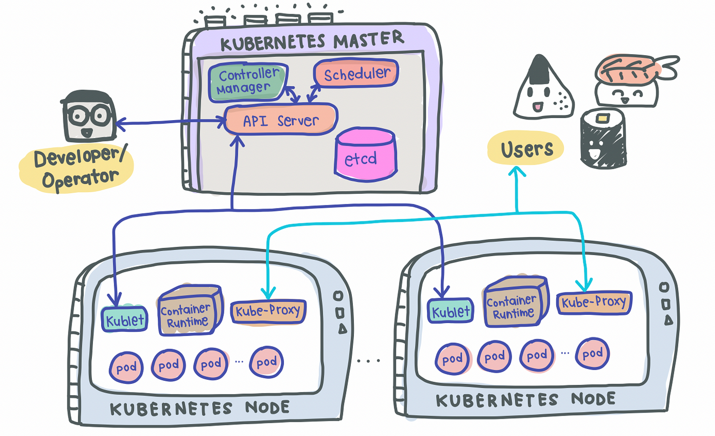
K8s uses a Master-Slave type of architecture where a node acts as the Master, calling the shots in the cluster while the other nodes act as slaves/worker nodes, executing application workloads decided by the Master.
A Simple Kubernetes Architecture
A simple K8s setup with a single Master node along with 2 worker nodes look something like this:
Master Node(s)
As its name suggests, the Master node is the boss of the cluster, deciding the cluster state and what each worker node does. In order to setup a Master node, 4 processes are required to run on it:
1. API Server
- Main entrypoint for users to interact with the cluster (i.e., cluster gateway); it is where requests are sent when we use
kubectl - Gatekeeper for authentication and request validation, ensuring that only certain users are able to execute requests
2. Scheduler
- Decide which node the next pod will be spun up on but does NOT spin up the pod itself (kubelet does this)
3. Controller Manager
- Detects cluster state changes (e.g., pods dying) and tries to restore the cluster back to its original state
- For example, if a pod unexpectedly dies, the Controller Manager makes a request to the Scheduler to decide which node to spin up the new pod to replace the dead pod. Kubelet then spins up the new pod.
4. etcd
- Cluster BRAIN!
- Key-Value store of the cluster state
- Any cluster changes made will be stored here
- Application data is NOT stored here, only cluster state data. Remember, the master node does not do the work, it is the brain of the cluster. Specifically, etcd stores the cluster state information in order for other processes above to know information about the cluster
Slave/Worker Node(s)
Each worker node has to be installed with 3 node processes in order to allow Kubernetes to interact with it and to independently spin up pods within each node. The 3 processes required are:
1. Kubelet a.k.a. kubelet
- Interacts with both the node AND the container
- In charge of taking configuration files and spinning up the pod using the container runtime (see below!) installed on the node
2. Container Runtime
- Any container runtime installed (e.g., Docker, containerd)
3. Kube Proxy a.k.a. kube-proxy
- A network proxy that implements part of the Kubernetes Service concept (details below)
- Sits between nodes and forwards the requests intelligently (either intra-node or inter-node forwarding)
Now that we know K8s work, let’s look at some of the most common components of Kubernetes that we will use to deploy our applications.
1. Pod
- Smallest unit of K8s and usually houses an instance of your application
- Abstraction over a container
- Each pod gets its own IP address (public or private)
- Ephemeral — new IP address upon re-creation of pod
2. Service
- Because pods are meant to be ephemeral, Service provides a way to “give” pods a permanent IP address
- With Service, if the pod dies, its IP address will not change upon re-creation
- Acts almost as a load balancer that routes traffic to pods while maintaining a static IP
- Like load balancers, the Service can also be internal or external, where external Service is public facing (public IP) and internal Service which is meant for internal applications (private IP)
3. Ingress
- With Services, we may now have a web application exposed on a certain port, say 8080 on an IP address, say 10.104.35. In practice, it is impractical to access a public-facing application on
http://10.104.35:8080. - We would thus need an entrypoint with a proper domain name (e.g.,
https://my-domain-name.com, which then forwards the request to the Service (e.g.,http://10.104.35:8080) - In essence, Ingress exposes HTTP and HTTPs routes from outside the cluster to services within the cluster [1].
- SSL termination (a.k.a. SSL offloading) — i.e., traffic to Service and its Pods is in plaintext
- That being said, creating an Ingress resource alone has no effect. An Ingress-controller is also required to satisfy an Ingress.
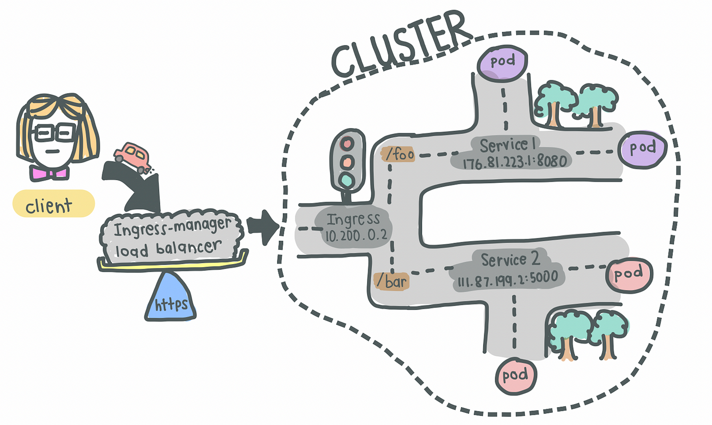
4. Ingress Controller
- Load balances incoming traffic to services in the cluster
- Also manages egress traffic for services that require communication with external services
What is the difference between Ingress and Ingress Controller?
Ingress contains the rules for routing traffic, deciding which Service the incoming request should route to within the cluster.
Ingress Controller is the actual implementation of Ingress, in charge of the Layer-4 or Layer-7 proxy. Examples of Ingress Controller include Ingress NGINX Controller and Ingress GCE. Each cloud provider and other 3rd party providers will have their own implementation of the Ingress Controller.
A full list can be found here.
5. ConfigMap
- As its name suggests, it is essentially a configuration file that you want exposed for users to modify
6. Secret
- Also a configuration file, but for sensitive information like passwords
- Base64-encoded
7. Volumes
- Used for persistent data storage
- As pods themselves are ephemeral, volumes are used to persist information so that existing and new pods can reference some state of your application
- Acts almost like an “external hard drive” for your pods
- Volumes can be stored locally on the same node running your pods or remotely (e.g., cloud storage, NFS)
8. Deployment
- Used to define blueprint for pods
- In practice, we deal with deployments and not pods themselves
- Deployments usually have replicas such that when any component of the application dies, there is always a backup
- However, components like databases cannot be replicated because they are stateful applications. In this case, we would need the Kubernetes component: StatefulSet. This is hard and more often than not, databases should be hosted outside the Kubernetes cluster
Ok, that was probably too much to digest. Let’s jump into some hands-on practice! Do take some time to re-read the above to get a clear understanding of each component’s responsibility in the entire K8s architecture.
Because this article focuses on understanding the components of K8s themselves rather than how to setup a K8s cluster, we will simply use minikube to setup our own local cluster. After which, we will deploy a simple but realistic application — a MLFlow server.
If you want to follow along with the source code, I have included them in a GitHub repo here.
What we will be setting up
A typical application has a web server with a backend service to persist data — that’s what we will aim to replicate and deploy today. To make things simpler, we’ll deploy a MLFlow web server that persists data on a Cloud SQL database on Google Cloud Platform (GCP).
The setup is shown below:
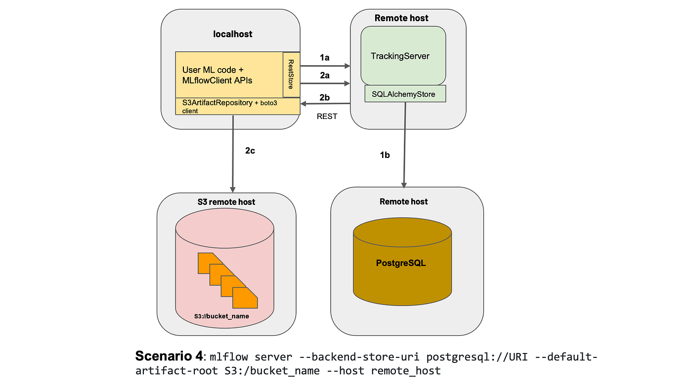
To those who are unaware, MLFlow is mainly an experiment tracking tool that allows Data Scientists to track their data science experiments by logging data and model artifacts, with the option of deploying their models using a standardized package defined by MLFlow. For the purposes of this article, we will deploy the MLFlow tracking web server with a PostgreSQL backend (hosted on Cloud SQL) and blob store (on Google Cloud Storage).
Before that, we’ll have to install a few things (skip ahead if you already have these installed).
Installation
- Docker
- K8s command line tool,
kubectl. Our best friend — we use this to interact with our K8s cluster, be it minikube, cloud or a hybrid cluster - Minikube installation guide
- Google Cloud SDK
- [Optional] Power tools for
kubectl,kubensandkubectx. Follow this to install.
Setting up your local cluster
Start your cluster with minikube start. That’s it! You’ve created your own local Kubernetes cluster with a single command 🙂
You can verify that the various components listed above are created with minikube status. If you have several K8s cluster context, make sure you switch to minikube.
# Check context
kubectx# If not on minikube, switch context
kubectx minikube
With our local cluster setup, let’s start by setting up external components and then move on to deploying Kubernetes objects.
1. Create a Dockerfile for MLFlow
We first need a Docker image of the MLFlow web server that we will be deploying. Unfortunately, MLFlow does not have an official image that we can use on DockerHub, so I’ve created one here for everyone to use. Let’s pull the image I’ve created from DockerHub.
docker pull davidcjw/example-mlflow:1.0
[Optional] To test if the image works locally, simply run:
docker run -p 8080:8080 davidcjw/example-mlflow:1.0
2. Create a Cloud SQL (PostgreSQL) instance on GCP
This will be used to store metadata for the runs logged onto MLFlow tracking server. As mentioned earlier, it is easier to create stateful applications outside of your Kubernetes cluster.
- First of all, create an account and project on GCP if you don’t already have one
- Create an instance using the CLI with the following command:
gcloud sql instances create <your_instance_name> \
--assign-ip \
--authorized-networks=<your_ip_address>/32 \
--database-version=POSTGRES_14 \
--region=<your_region> \
--cpu=2 \
--memory=3840MiB \
--root-password=<your_password>
To find <your_ip_address>, simple Google “what is my ip”. For <region>, you can specify a region that is close to you. For me, I’ve specified asia-southeast1.
NOTE! These configs are intended for this example deployment and not suitable for production environments. For production environments, you would want to have minimally multi-zonal availability connected over a Private IP.
3. Create a Google Cloud Storage Bucket
This will be used to store data and model artefacts logged by the user. Create a bucket on GCP and take note of the URI for later. For myself, I’ve created one at gs://example-mlflow-artefactsusing the following command:
gsutil mb -l <your_region> gs://example-mlflow-artefacts
4. Create ConfigMap and Secret on our local minikubecluster
Now, the exciting part — deploying onto our Kubernetes clusters the various components that are needed. Before that, it’s absolutely essential to know a few things about K8s objects.
Kubernetes resources are created using .yaml files with specific formats (refer to the Kubernetes documentation [2] for any resource type you’re creating). They are used to define what containerized applications are running on which port and more importantly, the policies around how those applications behave.
The .yaml files effectively defines our cluster state!
Describing Kubernetes Objects (.yaml files):
- Always starts with
apiVersion,kindand hasmetadata apiVersion: defines version number of the Kubernetes API (usually v1 if the version you are using is in stable mode)kind: defines the component type (e.g. Secret, ConfigMap, Pod, etc)metadata: data that uniquely identifies an object, includingname,UIDandnamespace(more about this in the future!)spec(or specification) /data: details specific to the component
4a. Let’s start with the ConfigMap as these configurations will be needed when we deploy our MLFlow application using Deployment (NOTE: Order of resource creation matters, especially when there is configurations or secrets attached to deployments).
# configmap.yaml
apiVersion: v1
kind: ConfigMap
metadata:
name: mlflow-configmap
data:
# property-like keys; each key maps to a simple value
DEFAULT_ARTIFACT_ROOT: <your_gs_uri>
DB_NAME: postgres
DB_USERNAME: postgres
DB_HOST: <your_cloud_sql_public_ip>
💡 Pro Tip! Always have a tab of the official K8s documentation open so you can reference the example
.yamlfile they have for each K8s component.
4b. Next, let’s create one for Secrets. Note that secrets have to be base64-encoded. It can simply be done using:
echo -n "<your_password>" | base64
The only thing that we have to encode is the password for our PostgreSQL instance defined above earlier when we created it on Cloud SQL. Let’s base64-encode that and copy the stdout into the .yaml file below.
# secrets.yaml
apiVersion: v1
kind: Secret
metadata:
name: mlflow-postgresql-credentials
type: Opaque
data:
postgresql-password: <your_base64_encoded_password>
Apply ConfigMap and Secret using:
kubectl apply -f k8s/configmap.yaml
kubectl apply -f k8s/secrets.yaml>>> configmap/mlflow-configmap created
>>> secret/mlflow-postgresql-credentials created
Great! We can now reference the secrets and configurations we have created.
5. Create Deployment and Service
5a. Let’s start with Deployment. To understand deployments, let’s take a step back and recall that the main difference between Deployment and Pod is that the former helps to create replicas of the pod that will be deployed. As such, the yaml file for Deployment consists of the configurations for the Pod, as well as the number of replicas we want to create.
If we take a look at the yaml file below, we notice metadata and spec appearing twice in the configuration, the first time at the top of the config file and the second time below the “template” key. This is because everything defined BELOW the “template” key is used for the Pod configuration.
Simply put, a Pod component deploys a single instance of our application whereas a Deployment (usually) consists of more than one deployment of that Pod. If the number of replicas in our Deployment is 1, it is essentially the same as a single Pod (but with the option of scaling up).
# deployment.yaml
apiVersion: apps/v1
kind: Deployment
metadata:
name: mlflow-tracking-server
labels:
app: mlflow-tracking-server
spec:
replicas: 1
selector:
matchLabels:
app: mlflow-tracking-server-pods
# Pod configurations defined here in `template`
template:
metadata:
labels:
app: mlflow-tracking-server-pods
spec:
containers:
- name: mlflow-tracking-server-pod
image: davidcjw/example-mlflow:1.0
ports:
- containerPorts: 5000
resources:
limits:
memory: 1Gi
cpu: "2"
requests:
memory: 1Gi
cpu: "1"
imagePullPolicy: Always
env:
- name: DB_PASSWORD
valueFrom:
secretKeyRef:
name: mlflow-postgresql-credentials
key: postgresql-password
- name: DB_USERNAME
valueFrom:
configMapKeyRef:
name: mlflow-configmap
key: DB_USERNAME
- name: DB_HOST
valueFrom:
configMapKeyRef:
name: mlflow-configmap
key: DB_HOST
- name: DB_NAME
valueFrom:
configMapKeyRef:
name: mlflow-configmap
key: DB_NAME
- name: DEFAULT_ARTIFACT_ROOT
valueFrom:
configMapKeyRef:
name: mlflow-configmap
key: DEFAULT_ARTIFACT_ROOT
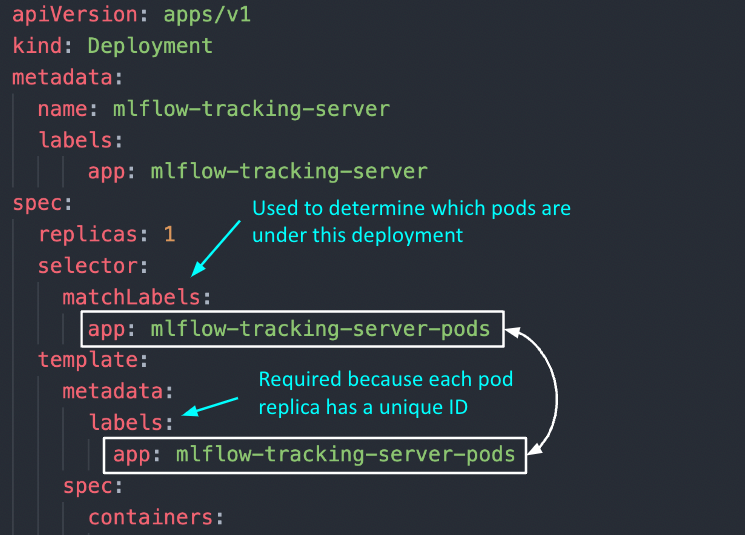
Two important questions to answer: 1) How do the pod replicas group together to be identified as one by the Deployment? 2) How does the Deployment know which group of pod replicas belong to it?
template > metadata > labels: Unlike other components like ConfigMap and Secret, this metadata keylabelsis mandatory because each pod replica created under this deployment will have a unique ID (e.g., mlflow-tracking-xyz, mlflow-tracking-abc). To be able to collectively identify them as a group, labels are used so that each of these pod replicas will receive these same set of labels.selector > matchLabels: Used to determine which group of pods are under this deployment. Note that the labels here have to exactly match the labels in (1).
Other key configurations:
replicas: used to determine the number of pod replicascontainers > image: the image that will be used by each podcontainers > env: here is where we specify the environment variables that will be initialized in each pod, referenced from the ConfigMap and Secret we have created earlier.
5b. Service — As mentioned above, Service is used almost like a load balancer to distribute traffic to each of the pod replicas. As such, here are some important things to note about Service.
selector: This key-value pair should match thetemplate > metadata > labelsspecified earlier in Deployment, so that Service knows which set of pods to route the request to.type: This defaults toClusterIP, which is the internal IP address of the cluster (a list of other other service types can be found here). For our use case, we will useNodePortto expose our web application on a port of our node’s IP address. Do note that the values forNodePortcan only be between 30000–32767.targetPort: This refers to the port that your pod is exposing the application on, which is specified in Deployment.
apiVersion: v1
kind: Service
metadata:
labels:
app: mlflow-tracking-server
name: mlflow-tracking-server
spec:
type: NodePort
selector:
app: mlflow-tracking-server-pods
ports:
- port: 5000
protocol: TCP
targetPort: 5000
nodePort: 30001
5c. Putting it together
You can in fact put several .yaml configurations in one file — specifically the Deployment and Service configurations, since we will be applying those changes together. To do so, simply use a --- to demarcate these two configs in one file:
# deployment.yaml
apiVersion: v1
kind: Deployment
...
---
apiVersion: v1
kind: Service
...
Finally, we apply these changes using kubectl apply -f k8s/deployment.yaml. Congrats! You can now access your MLFlow server at <node_IP>:<nodePort>. Here’s how to find out what your node_IP is:
kubectl get node -o wide# or equivalently:
minikube ip
If you’re a Apple Silicon or Windows user…
If you’re like me using the Docker driver on Darwin (or Windows, WSL), the Node IP will not be directly reachable using the above method. Complete steps 4 and 5 listed in this link to access your application.
Cleaning Up
Finally, we’re done with our test application and cleaning up is as simple as minikube delete --all.
Thanks for reading and hope this helps you in your understanding of Kubernetes. Please let me know if you spot any mistakes or if you would like to know more in another article!
[1] What is Ingress?
[2] Kubernetes Documentation
[3] Nana’s Kubernetes Crash Course
[4] Accessing apps (Minikube)
It doesn’t have to be that complicated, right?
With a hands-on MLFlow deployment example
If you’re reading this article, it’s likely because you’ve heard this buzzword “Kubernetes” (K8s) and you’re likely to be in the technology space. You would also likely have some idea of what containerization (or synonymously known as Docker / dockerization) is, so I would skip over the details of that and jump straight into what K8s is.
In a nutshell, K8s is simply a container orchestration framework. What this essentially means is that K8s is a system designed to automate the lifecycle of containerized applications — from predictability, scalability to availability.
Why do we even need Kubernetes?
The driving reason behind the rise and need for K8s stems from the increasing use of microservices, away from traditional monolithic-type applications. As a result, containers provide the perfect host for these individual microservices as containers manage dependencies, are independent, OS-agnostic and ephemeral, amongst other benefits.
Complex applications that have many components are often made up of hundreds or even thousands of microservices. Scaling these microservices up while ensuring availability is an extremely painful process if we were to manage all these different components using custom-written programs or scripts, resulting in the demand for a proper way of managing these components.
Cue Kubernetes.
Benefits of Kubernetes
Kubernetes promises to solve the above problem using these following features:
- High Availability — this simply means that your application will always be up and running, whether you have a new update to roll-out or have some unexpected pods crashing.
- Scalability — this ensures high performance of your application, whether you have a single user or a thousand users flooding your application concurrently.
- Disaster Recovery — this ensures that your application will always have the latest data and states of your application if something unfortunate happens to your physical or cloud-based infrastructure.
K8s uses a Master-Slave type of architecture where a node acts as the Master, calling the shots in the cluster while the other nodes act as slaves/worker nodes, executing application workloads decided by the Master.
A Simple Kubernetes Architecture
A simple K8s setup with a single Master node along with 2 worker nodes look something like this:
Master Node(s)
As its name suggests, the Master node is the boss of the cluster, deciding the cluster state and what each worker node does. In order to setup a Master node, 4 processes are required to run on it:
1. API Server
- Main entrypoint for users to interact with the cluster (i.e., cluster gateway); it is where requests are sent when we use
kubectl - Gatekeeper for authentication and request validation, ensuring that only certain users are able to execute requests
2. Scheduler
- Decide which node the next pod will be spun up on but does NOT spin up the pod itself (kubelet does this)
3. Controller Manager
- Detects cluster state changes (e.g., pods dying) and tries to restore the cluster back to its original state
- For example, if a pod unexpectedly dies, the Controller Manager makes a request to the Scheduler to decide which node to spin up the new pod to replace the dead pod. Kubelet then spins up the new pod.
4. etcd
- Cluster BRAIN!
- Key-Value store of the cluster state
- Any cluster changes made will be stored here
- Application data is NOT stored here, only cluster state data. Remember, the master node does not do the work, it is the brain of the cluster. Specifically, etcd stores the cluster state information in order for other processes above to know information about the cluster
Slave/Worker Node(s)
Each worker node has to be installed with 3 node processes in order to allow Kubernetes to interact with it and to independently spin up pods within each node. The 3 processes required are:
1. Kubelet a.k.a. kubelet
- Interacts with both the node AND the container
- In charge of taking configuration files and spinning up the pod using the container runtime (see below!) installed on the node
2. Container Runtime
- Any container runtime installed (e.g., Docker, containerd)
3. Kube Proxy a.k.a. kube-proxy
- A network proxy that implements part of the Kubernetes Service concept (details below)
- Sits between nodes and forwards the requests intelligently (either intra-node or inter-node forwarding)
Now that we know K8s work, let’s look at some of the most common components of Kubernetes that we will use to deploy our applications.
1. Pod
- Smallest unit of K8s and usually houses an instance of your application
- Abstraction over a container
- Each pod gets its own IP address (public or private)
- Ephemeral — new IP address upon re-creation of pod
2. Service
- Because pods are meant to be ephemeral, Service provides a way to “give” pods a permanent IP address
- With Service, if the pod dies, its IP address will not change upon re-creation
- Acts almost as a load balancer that routes traffic to pods while maintaining a static IP
- Like load balancers, the Service can also be internal or external, where external Service is public facing (public IP) and internal Service which is meant for internal applications (private IP)
3. Ingress
- With Services, we may now have a web application exposed on a certain port, say 8080 on an IP address, say 10.104.35. In practice, it is impractical to access a public-facing application on
http://10.104.35:8080. - We would thus need an entrypoint with a proper domain name (e.g.,
https://my-domain-name.com, which then forwards the request to the Service (e.g.,http://10.104.35:8080) - In essence, Ingress exposes HTTP and HTTPs routes from outside the cluster to services within the cluster [1].
- SSL termination (a.k.a. SSL offloading) — i.e., traffic to Service and its Pods is in plaintext
- That being said, creating an Ingress resource alone has no effect. An Ingress-controller is also required to satisfy an Ingress.
4. Ingress Controller
- Load balances incoming traffic to services in the cluster
- Also manages egress traffic for services that require communication with external services
What is the difference between Ingress and Ingress Controller?
Ingress contains the rules for routing traffic, deciding which Service the incoming request should route to within the cluster.
Ingress Controller is the actual implementation of Ingress, in charge of the Layer-4 or Layer-7 proxy. Examples of Ingress Controller include Ingress NGINX Controller and Ingress GCE. Each cloud provider and other 3rd party providers will have their own implementation of the Ingress Controller.
A full list can be found here.
5. ConfigMap
- As its name suggests, it is essentially a configuration file that you want exposed for users to modify
6. Secret
- Also a configuration file, but for sensitive information like passwords
- Base64-encoded
7. Volumes
- Used for persistent data storage
- As pods themselves are ephemeral, volumes are used to persist information so that existing and new pods can reference some state of your application
- Acts almost like an “external hard drive” for your pods
- Volumes can be stored locally on the same node running your pods or remotely (e.g., cloud storage, NFS)
8. Deployment
- Used to define blueprint for pods
- In practice, we deal with deployments and not pods themselves
- Deployments usually have replicas such that when any component of the application dies, there is always a backup
- However, components like databases cannot be replicated because they are stateful applications. In this case, we would need the Kubernetes component: StatefulSet. This is hard and more often than not, databases should be hosted outside the Kubernetes cluster
Ok, that was probably too much to digest. Let’s jump into some hands-on practice! Do take some time to re-read the above to get a clear understanding of each component’s responsibility in the entire K8s architecture.
Because this article focuses on understanding the components of K8s themselves rather than how to setup a K8s cluster, we will simply use minikube to setup our own local cluster. After which, we will deploy a simple but realistic application — a MLFlow server.
If you want to follow along with the source code, I have included them in a GitHub repo here.
What we will be setting up
A typical application has a web server with a backend service to persist data — that’s what we will aim to replicate and deploy today. To make things simpler, we’ll deploy a MLFlow web server that persists data on a Cloud SQL database on Google Cloud Platform (GCP).
The setup is shown below:
To those who are unaware, MLFlow is mainly an experiment tracking tool that allows Data Scientists to track their data science experiments by logging data and model artifacts, with the option of deploying their models using a standardized package defined by MLFlow. For the purposes of this article, we will deploy the MLFlow tracking web server with a PostgreSQL backend (hosted on Cloud SQL) and blob store (on Google Cloud Storage).
Before that, we’ll have to install a few things (skip ahead if you already have these installed).
Installation
- Docker
- K8s command line tool,
kubectl. Our best friend — we use this to interact with our K8s cluster, be it minikube, cloud or a hybrid cluster - Minikube installation guide
- Google Cloud SDK
- [Optional] Power tools for
kubectl,kubensandkubectx. Follow this to install.
Setting up your local cluster
Start your cluster with minikube start. That’s it! You’ve created your own local Kubernetes cluster with a single command 🙂
You can verify that the various components listed above are created with minikube status. If you have several K8s cluster context, make sure you switch to minikube.
# Check context
kubectx# If not on minikube, switch context
kubectx minikube
With our local cluster setup, let’s start by setting up external components and then move on to deploying Kubernetes objects.
1. Create a Dockerfile for MLFlow
We first need a Docker image of the MLFlow web server that we will be deploying. Unfortunately, MLFlow does not have an official image that we can use on DockerHub, so I’ve created one here for everyone to use. Let’s pull the image I’ve created from DockerHub.
docker pull davidcjw/example-mlflow:1.0
[Optional] To test if the image works locally, simply run:
docker run -p 8080:8080 davidcjw/example-mlflow:1.0
2. Create a Cloud SQL (PostgreSQL) instance on GCP
This will be used to store metadata for the runs logged onto MLFlow tracking server. As mentioned earlier, it is easier to create stateful applications outside of your Kubernetes cluster.
- First of all, create an account and project on GCP if you don’t already have one
- Create an instance using the CLI with the following command:
gcloud sql instances create <your_instance_name> \
--assign-ip \
--authorized-networks=<your_ip_address>/32 \
--database-version=POSTGRES_14 \
--region=<your_region> \
--cpu=2 \
--memory=3840MiB \
--root-password=<your_password>
To find <your_ip_address>, simple Google “what is my ip”. For <region>, you can specify a region that is close to you. For me, I’ve specified asia-southeast1.
NOTE! These configs are intended for this example deployment and not suitable for production environments. For production environments, you would want to have minimally multi-zonal availability connected over a Private IP.
3. Create a Google Cloud Storage Bucket
This will be used to store data and model artefacts logged by the user. Create a bucket on GCP and take note of the URI for later. For myself, I’ve created one at gs://example-mlflow-artefactsusing the following command:
gsutil mb -l <your_region> gs://example-mlflow-artefacts
4. Create ConfigMap and Secret on our local minikubecluster
Now, the exciting part — deploying onto our Kubernetes clusters the various components that are needed. Before that, it’s absolutely essential to know a few things about K8s objects.
Kubernetes resources are created using .yaml files with specific formats (refer to the Kubernetes documentation [2] for any resource type you’re creating). They are used to define what containerized applications are running on which port and more importantly, the policies around how those applications behave.
The .yaml files effectively defines our cluster state!
Describing Kubernetes Objects (.yaml files):
- Always starts with
apiVersion,kindand hasmetadata apiVersion: defines version number of the Kubernetes API (usually v1 if the version you are using is in stable mode)kind: defines the component type (e.g. Secret, ConfigMap, Pod, etc)metadata: data that uniquely identifies an object, includingname,UIDandnamespace(more about this in the future!)spec(or specification) /data: details specific to the component
4a. Let’s start with the ConfigMap as these configurations will be needed when we deploy our MLFlow application using Deployment (NOTE: Order of resource creation matters, especially when there is configurations or secrets attached to deployments).
# configmap.yaml
apiVersion: v1
kind: ConfigMap
metadata:
name: mlflow-configmap
data:
# property-like keys; each key maps to a simple value
DEFAULT_ARTIFACT_ROOT: <your_gs_uri>
DB_NAME: postgres
DB_USERNAME: postgres
DB_HOST: <your_cloud_sql_public_ip>
💡 Pro Tip! Always have a tab of the official K8s documentation open so you can reference the example
.yamlfile they have for each K8s component.
4b. Next, let’s create one for Secrets. Note that secrets have to be base64-encoded. It can simply be done using:
echo -n "<your_password>" | base64
The only thing that we have to encode is the password for our PostgreSQL instance defined above earlier when we created it on Cloud SQL. Let’s base64-encode that and copy the stdout into the .yaml file below.
# secrets.yaml
apiVersion: v1
kind: Secret
metadata:
name: mlflow-postgresql-credentials
type: Opaque
data:
postgresql-password: <your_base64_encoded_password>
Apply ConfigMap and Secret using:
kubectl apply -f k8s/configmap.yaml
kubectl apply -f k8s/secrets.yaml>>> configmap/mlflow-configmap created
>>> secret/mlflow-postgresql-credentials created
Great! We can now reference the secrets and configurations we have created.
5. Create Deployment and Service
5a. Let’s start with Deployment. To understand deployments, let’s take a step back and recall that the main difference between Deployment and Pod is that the former helps to create replicas of the pod that will be deployed. As such, the yaml file for Deployment consists of the configurations for the Pod, as well as the number of replicas we want to create.
If we take a look at the yaml file below, we notice metadata and spec appearing twice in the configuration, the first time at the top of the config file and the second time below the “template” key. This is because everything defined BELOW the “template” key is used for the Pod configuration.
Simply put, a Pod component deploys a single instance of our application whereas a Deployment (usually) consists of more than one deployment of that Pod. If the number of replicas in our Deployment is 1, it is essentially the same as a single Pod (but with the option of scaling up).
# deployment.yaml
apiVersion: apps/v1
kind: Deployment
metadata:
name: mlflow-tracking-server
labels:
app: mlflow-tracking-server
spec:
replicas: 1
selector:
matchLabels:
app: mlflow-tracking-server-pods
# Pod configurations defined here in `template`
template:
metadata:
labels:
app: mlflow-tracking-server-pods
spec:
containers:
- name: mlflow-tracking-server-pod
image: davidcjw/example-mlflow:1.0
ports:
- containerPorts: 5000
resources:
limits:
memory: 1Gi
cpu: "2"
requests:
memory: 1Gi
cpu: "1"
imagePullPolicy: Always
env:
- name: DB_PASSWORD
valueFrom:
secretKeyRef:
name: mlflow-postgresql-credentials
key: postgresql-password
- name: DB_USERNAME
valueFrom:
configMapKeyRef:
name: mlflow-configmap
key: DB_USERNAME
- name: DB_HOST
valueFrom:
configMapKeyRef:
name: mlflow-configmap
key: DB_HOST
- name: DB_NAME
valueFrom:
configMapKeyRef:
name: mlflow-configmap
key: DB_NAME
- name: DEFAULT_ARTIFACT_ROOT
valueFrom:
configMapKeyRef:
name: mlflow-configmap
key: DEFAULT_ARTIFACT_ROOT
Two important questions to answer: 1) How do the pod replicas group together to be identified as one by the Deployment? 2) How does the Deployment know which group of pod replicas belong to it?
template > metadata > labels: Unlike other components like ConfigMap and Secret, this metadata keylabelsis mandatory because each pod replica created under this deployment will have a unique ID (e.g., mlflow-tracking-xyz, mlflow-tracking-abc). To be able to collectively identify them as a group, labels are used so that each of these pod replicas will receive these same set of labels.selector > matchLabels: Used to determine which group of pods are under this deployment. Note that the labels here have to exactly match the labels in (1).
Other key configurations:
replicas: used to determine the number of pod replicascontainers > image: the image that will be used by each podcontainers > env: here is where we specify the environment variables that will be initialized in each pod, referenced from the ConfigMap and Secret we have created earlier.
5b. Service — As mentioned above, Service is used almost like a load balancer to distribute traffic to each of the pod replicas. As such, here are some important things to note about Service.
selector: This key-value pair should match thetemplate > metadata > labelsspecified earlier in Deployment, so that Service knows which set of pods to route the request to.type: This defaults toClusterIP, which is the internal IP address of the cluster (a list of other other service types can be found here). For our use case, we will useNodePortto expose our web application on a port of our node’s IP address. Do note that the values forNodePortcan only be between 30000–32767.targetPort: This refers to the port that your pod is exposing the application on, which is specified in Deployment.
apiVersion: v1
kind: Service
metadata:
labels:
app: mlflow-tracking-server
name: mlflow-tracking-server
spec:
type: NodePort
selector:
app: mlflow-tracking-server-pods
ports:
- port: 5000
protocol: TCP
targetPort: 5000
nodePort: 30001
5c. Putting it together
You can in fact put several .yaml configurations in one file — specifically the Deployment and Service configurations, since we will be applying those changes together. To do so, simply use a --- to demarcate these two configs in one file:
# deployment.yaml
apiVersion: v1
kind: Deployment
...
---
apiVersion: v1
kind: Service
...
Finally, we apply these changes using kubectl apply -f k8s/deployment.yaml. Congrats! You can now access your MLFlow server at <node_IP>:<nodePort>. Here’s how to find out what your node_IP is:
kubectl get node -o wide# or equivalently:
minikube ip
If you’re a Apple Silicon or Windows user…
If you’re like me using the Docker driver on Darwin (or Windows, WSL), the Node IP will not be directly reachable using the above method. Complete steps 4 and 5 listed in this link to access your application.
Cleaning Up
Finally, we’re done with our test application and cleaning up is as simple as minikube delete --all.
Thanks for reading and hope this helps you in your understanding of Kubernetes. Please let me know if you spot any mistakes or if you would like to know more in another article!
[1] What is Ingress?
[2] Kubernetes Documentation
[3] Nana’s Kubernetes Crash Course
[4] Accessing apps (Minikube)
Denial of responsibility! Techno Blender is an automatic aggregator of the all world’s media. In each content, the hyperlink to the primary source is specified. All trademarks belong to their rightful owners, all materials to their authors. If you are the owner of the content and do not want us to publish your materials, please contact us by email – [email protected]. The content will be deleted within 24 hours.